
Hub and spoke topology is often recommended in cloud architectures for several reasons:
- Simplicity: Hub and spoke networks are relatively simple to set up and manage, which makes them a good choice for cloud environments where resources may be scarce or limited.
- Cost-effectiveness: In a cloud environment, resources are typically shared among multiple users or tenants, which makes cost-effectiveness a key consideration. Hub and spoke networks are generally more cost-effective than other types of network topologies, as they require fewer connections and a simpler management.
- Scalability: Cloud environments are designed to be highly scalable, and the hub and spoke topology is easily scalable, as additional spokes can be easily added to the network by connecting them to the central hub.
- Performance: In a cloud environment, it is important to optimize performance to ensure that users have a good experience. Hub and spoke networks can be configured to optimize performance, as the central hub can be used to route traffic and balance the load on the network.
- Security: Hub and spoke networks can be configured to provide enhanced security by implementing measures such as firewalls and intrusion detection systems at the central hub. This can help protect the network and the data it carries from external threats.
Overall, the simplicity, cost-effectiveness, scalability, performance, and security of hub and spoke networks make them a good choice for many cloud architectures.
Often a single hub may not be sufficient for an organization. There are several reasons why an organization might need to implement more than one hub and spoke topology in a cloud environment:
- Redundancy: In a cloud environment, it is important to have redundancy in place to ensure that the network is highly available and resilient to failures. Implementing multiple hub and spoke topologies can provide additional redundancy and ensure that the network remains operational in the event of a failure.
- Scale: As an organization’s cloud environment grows, it may need to implement additional hub and spoke topologies to support the increased number of devices, services and users on the network.
- Performance: If an organization has a large number of devices and users on its network, it may need to implement multiple hub and spoke topologies to optimize performance. By distributing the load across multiple hubs, the organization can ensure that the network performs well and provides a good experience for all users.
- Security: Implementing multiple hub and spoke topologies can help to enhance security in a cloud environment. For example, an organization might use separate hub and spoke topologies for different types of data or for different user groups, in order to better protect sensitive information (test, production…)
- Geography: If an organization has users and devices located in different geographic regions, it might need to implement multiple hub and spoke topologies to provide local connectivity and optimize performance for users in each region.
Overall, there are many reasons why an organization might need to implement more than one hub and spoke topology in a cloud environment. By carefully planning and designing the network, an organization can ensure that it has the resources and capabilities it needs to support its cloud environment and its users.
When multiple Hubs are in place, often a cross hub communication and routing is required.
In this blog article, I’ll show you how to arrange the routing between two Hubs that are peering with each other so that all spokes in both Hubs can communicate with one other.
This is an approach that, once understood, can be extended to scenarios with more than 2 Hubs easily.
The entire configuration is described by the following schema:
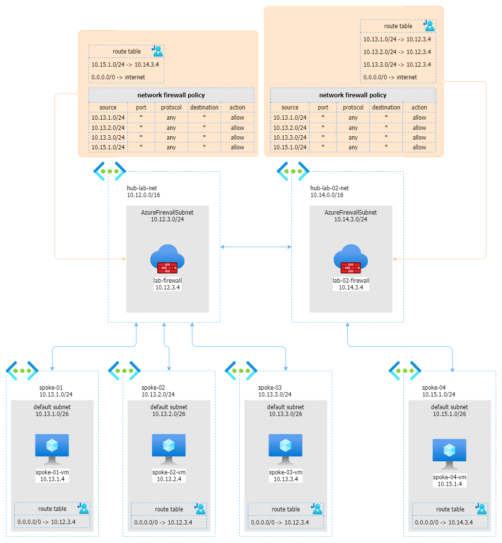
As you can see, we have 2 Hubs, the first one with 3 peering networks and the second with one peered network. These 2 Hubs are connected to each other with an additional peering.
The first step is to ensure that all outbound traffic from each peered network is forwarded to the corresponding firewall in the Hub. This is easly accomplished with a user-defined route as described below:
| spoke | user defined route table |
|---|---|
| spoke-01 | 0.0.0.0/0 -> 10.12.3.4 (firewall IP on Hub 1) |
| spoke-02 | 0.0.0.0/0 -> 10.12.3.4 (firewall IP on Hub 1) |
| spoke-03 | 0.0.0.0/0 -> 10.12.3.4 (firewall IP on Hub 1) |
| spoke-04 | 0.0.0.0/0 -> 10.14.3.4 (firewall IP on Hub 2) |
The second step regards tjhe firewalls, on each firewall (here we are using 2 Azure Firewalls), we need to ensure that any source network can reach any target network. This is possibile with the following network policy rule, associated to both firewalls:
| source | port | destination | action |
|---|---|---|---|
| 10.13.1.0/24 | any | * | allow |
| 10.13.2.0/24 | any | * | allow |
| 10.13.3.0/24 | any | * | allow |
| 10.13.4.0/24 | any | * | allow |
If you want to block some protocol, port or IP, this is easily possible working on the specific Hub policy.
As third step, you have to instruct the hub-lab-net firewall that spoke-04 is reachable through the hub-lab-02-net firewall. Also, all outbound traffic must be routed to the Internet. This is possible with the following user-defined route on firewall’s subnet:
- 10.15.1.0/24 (spoke-04 network) -> 10.14.3.4 (firewall in hub-lab-02-net)
- 0.0.0.0/0 -> internet
In the same way the hub-lab-02-net firewasll needs to know where to forward traffic for hub-lab-net’s spokes
- 10.13.1.0/24 (spoke-01 network) -> 10.13.3.4 (firewall in hub-lab-net)
- 10.13.2.0/24 (spoke-02 network) -> 10.13.3.4 (firewall in hub-lab-net)
- 10.13.3.0/24 (spoke-03 network) -> 10.13.3.4 (firewall in hub-lab-net)
- 0.0.0.0/0 -> internet
…and that’all folks! Now, from any machine, on any spoke, you can reach all the others.
On this page you can find a detailed step by step walktrough to implement this scenario.
The above walktrough is part of The Azure hub and spoke playground: a GitHub repo where you can find a reference network architecture I use as common base to implement configurations and test networking and connectivity scenarios.
More information:
- Azure Hub and Spoke playground on GitHub
- Azure hub-spoke network topology explained in the Azure Architecture center
- What is the Azure Firewall
- Understanding Azure Firewall policies
- How Azure custom routes work.